- Phase Failure Relays
- Monitoring Relays
- Motor / Pump Protection Relays
- Electronics Timers
- Liquid Level Controllers
- Power Line Transducers And MFM
- Automation Products
- Alarm Annunciators
- Products For Agri Sector
Potential Free Inputs
Potential Inputs
Alarm Annunciator
Automation Products
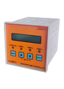
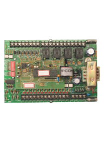
F3 BPC1 / F5 BPC1
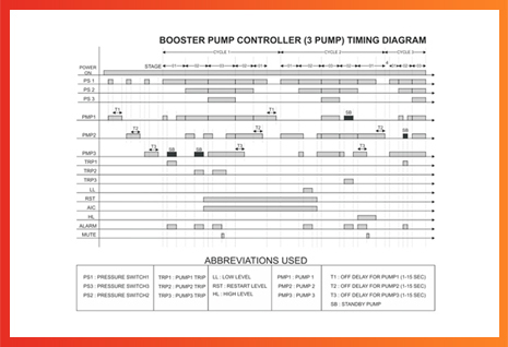
Sequencing of Booster Pumps according to the pressure switch, duty cycle is a necessity in a Booster Pump Control System. Minilec Booster Pump Controller fulfils all the requirements of a Booster Pump Control Panel. Suitable for 2/3 Pumps or 4/5 Pumps.
F3 BPC1 is suitable for 2/3 pumps and F5 BPC1 is suitable for 4/5 pumps, operates on 90-270 V AC/DC supply and has RS 485 output port.
Technical Data
- Parameter F3 BPC1 F5 BPC1
- Auxiliary Supply Voltage 90-270 V AC / DC 90-270 V AC / DC
- Pressure Switch Contacts 3 5
- Trip Contacts 3 5
- Water Level Inputs (4 Electrodes) HLL, LL & RST HLL, LL & RST
- Auto / Manual Selection By Front KeysBy Front Keys
- Alarm Mute By Front Keys By Front Keys
Inputs (Potential free)
- Pump 3 5
- Alarm 1 1
Relay Outputs
Serial Port Output (Optional)
RS 485Optinal
- Indications Power On, Power On
- Pump 1 On, Pump 1 On,
- Pump 2 On, Pump 2 On,
- Pump 3 On, Pump 3 On,
- Pump 4 On,
- Pump 5 On,
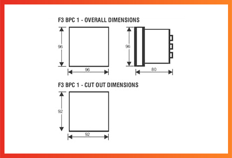
- Overall (L x W x D) 96 X 96 X 137 216 X 166 X 82
- Mounting (L x W) 92 X 92 203 X 153
Dimensions (mm)
- Weight 550 gms 850 gms
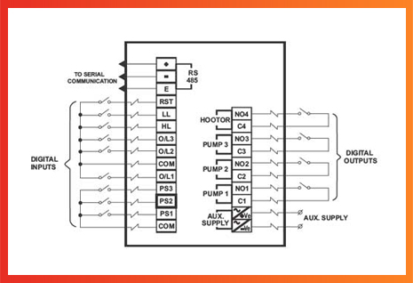
- 2, 3, 4,5 Pressure Switches
- Over load relay contacts
- Water Level Electrodes & Auto/Manual switches
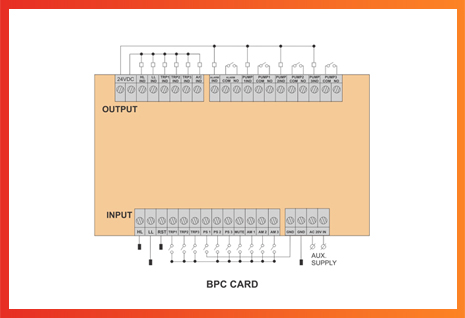
Input
- 2 Relay outputs for 2 Pump System OR 3 relay outputs for 3 pump System and respectively for 4 & 5 pump systems.
- Common Alarm Relay output for Buzzer.
Outputs
- For LED indications for RUN/Trip on the panel door For LED indications for LL, HL, O/L on the panel door
Open Collector output
- The key of the Booster Pumps is the Pressure Switches, which are preset according to the different pressure levels in the Pressure Tank. The water pressure in the Pressure Tank is to be maintained so that the consumers get constant pressure irrespective of the variations in the demand. As the user demand increases the respective Pressure switches activate & Booster Pumps are switched ON sequentially.
*Pumps are switched off Sequentially as per decrease in demand. Role of Stand-by pump is rotated in each next cycle to ensure equal running of all pumps.
