Nowadays 2 or more power sources are used for continuous power availability in infrastructure sectors like Commercial buildings, Malls, Hospitals… even in the Telecommunication sector (BTS) & in Industries also. As a power backup mostly DG sets are used as alternatives in case of break or failure of power supply from the Electricity Board. Depending on power demand 2 DGs are used for fulfilling total power requirement. Due to today’s growing India’s power demand, some of the sites have power from Electricity Board, DG & Solar/Wind power also. Hence it becomes important to monitor reverse power & protect the systems.
One of the solutions is to use a reverse power relay, it is a directional protective relay, which protects the back flow of power in reverse direction. A relay is used to prevent back flow of power either from an active generator to the utility or vice versa or 2nd generator when a generator operates in parallel with another generator or Utility or Solar or Wind. Because of lead/lag or high frequency or power factor or efficiency of the load or power regenerative loads cause reverse power which will be sensed by Minilec relay & trips breaker by make or break of supply to trip/shunt coil of Breaker. Voltage and current should be AC sinusoidal waveforms 50Hz /60Hz, no matter of its source of supply. System Neutral & load Neutral should be connected to corresponding terminals. Neutral should not be floated. Even earthings should also be properly provided. Reverse Power Relay protects generators’ damages (prime mover, turbine or engine) & prevents fire or explosions that may be caused by unburned fuel in the generator.
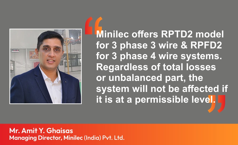
Minilec offers RPTD2 model for 3 phase 3 wire & RPFD2 for 3 phase 4 wire systems. Regardless of total losses or unbalanced part, the system will not be affected if it is at a permissible level.
RPTD2 requires a single-phase current and the phase-to- phase voltage; hence it is suitably representing three-phase power. For balanced three-phase conditions one RPTD2 can be used. If reverse power exceeds set trip value, the unit will change over its relay contacts to trip the breaker.
For balanced 3 phase, 4 wire system conditions, use RPFD2, connect phase-to- neutral voltage and the associated phase current. us, relay will measure the real power flowing in the particular phase to which the RPFD2 is connected. It is suitably monitoring single phase power which is representing three-phase forward power of the balanced system. Hence RPFD2 can be used as a reverse power monitoring Relay for single-phase and 3 ph 4 w balanced systems.
Solution on Reverse Power Monitoring by Minilec (Relay Model- RPT/RPFD2) Minilec offers RPTD2 model for 3 phase 3 wire & RPFD2 for 3 phase 4 wire systems. Regardless of total losses or unbalanced part, the system will not be affected if it is at a permissible level. Mr. Amit Y. Ghaisas Managing Director, Minilec (India) Pvt. Ltd. www.electricalpowerinfo.com Electrical & Power Info April-May 2022 063 For balanced voltages but unbalanced currents, one RPFD2 relay may be used but it will only measure the power in the phase to which it is connected. If both the voltages, currents are unbalanced & it is high, then we recommend to use 3 no’s of RPFD2, one for each individual phase & Neutral for 3 ph 4 w system. Depending on type of load & power source, reverse power range can be set between 2 to 20 % & time delay adjustment up to 10 sec., so that nuisance tripping due to transients encountered during synchronising can be avoided. Relay has an Auto/ Manual resetting facility. Trip setting for DG can be on the higher side whereas for Turbine it will be on the lower side.
Relay calculates power, representing the active power. If the active power becomes negative and exceeds the set level (2 – 20%), LED will indicate and the delay timer will be started. Relay contacts can be used for trip circuits. Refer our manual for the same.
Precautions – e signal should be pure sine wave. If the load is regenerative type, then the unit will sense reverse power & trips. Hence by using a power analyser please check the reverse current condition when the unit is tripping during your testing. Check that the voltage and current inputs have the correct phase relationship and the phase sequence is correct. Please note fault voltage and current magnitude depend on several factors, including source strength, location of fault, type of fault, system conditions, etc.
Make your power system more efficient & help the nation in controlling electrical power.
Please contact us –
Girish M. Vaidya
Marketing Head, Minilec (India) Pvt. Ltd., Pune
Tel: 020-67920100 Mobile: 9822057064
Email: mkt1@minilecgroup.com
Website: www.minilecgroup.com
Newsletter from minilec
